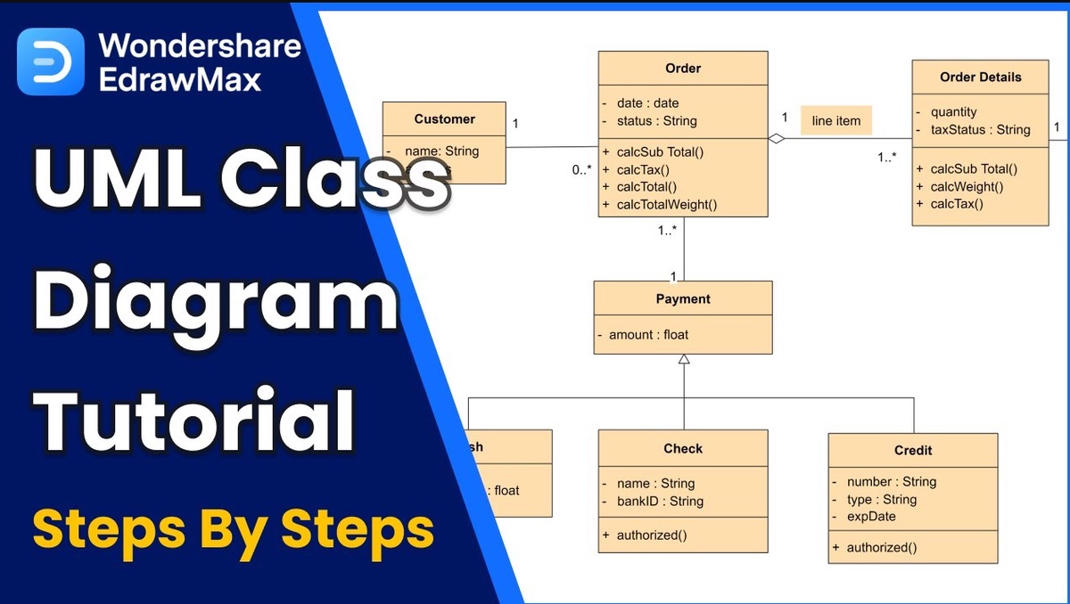
A UML Diagram is a graphical illustration of any idea that tells you how a system will look in a static form. It helps business managers and programmers brainstorm ideas on how to make it better during the developmental stages of any product.
A good UML diagram has detailed class structures, well-defined relationships, and visible information. However, creating such a thing can be an exhausting task. So, turning towards drawing tools seems just right.
Although there are multiple options out there, the built-in template library and a wide range of symbols make EdrawMax an excellent option. Here is how you can create UML diagrams in just five steps on this design tool.
Create a UML Diagram on EdrawMax in 5 Simple Steps
You can make UML diagrams in two ways on EdrawMax. Either with the help of its extensive symbol library or using an editable template. Here is how to create a UML diagram using EdrawMax templates:
-
Create a UML Diagram
- Open the online version of EdrawMax or its Desktop application.
- Log in or sign up if you don’t have an account.
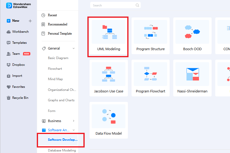
- Click New > Software and Database > Software Development > UML Diagram from the main menu.
- Press the Add icon to open the editing page.
-
Use the Symbol Library
- There is an extensive symbol library on the left side of this editing page. You will find task-specific components and shapes for structural and behavioral UML diagrams. Drag and drop components from this library on the blank canvas.
- Now, build connections between these components by using the floating buttons surrounding each shape.
-
Use Editable Templates
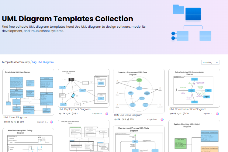
- Log into your account on the EdrawMax application. Click Templates and type UML Diagrams in the search panel from the main menu.
- This will open the UML template library. It has examples for Class, Activity, Use Case, Communication UML diagram, etc. Scroll down to find the one that is specific to your requirements and press the Use Immediately button.
- Once done, the template will move to the editing page for customizations. Add or remove symbols to this according to your task needs.
-
Customize the UML Diagram
- Next, change its themes, layout, and color scheme from the top menu
- You can also alter the relationships, symbols, and other components of the UML diagram.
-
Export the UML Diagram
- Click File Menu > Export > Option of your choice and download your UML diagram in any available format (PNG, XSL, PPT, Word, and SVG).
- Alternatively, click Save As option to directly save your diagrams in .eddx format.
EdrawMax is the Solution to Create Quick UML Diagrams
EdrawMax is a unique UML Diagram tool with a large and versatile symbol library. Its easy-to-use interface and built-in templates make the process quick and simple. Here is everything that makes this drawing tool a smart alternative for basic and lengthy UML diagrams.
- Versatile Symbol Collection: The EdrawMax UML diagram creator has a large symbol library. It is in the left corner of the editing panel with easily accessible symbols. It has Class, Use Case, Sequence, and other chart-specific symbols. So, all you need is to drag and drop the task-specific symbol on your blank canvas and build connections.
- Extensive Template Library: Wondershare EdrawMax supports a large collection of ready-made templates. These include subdivisions of both categories, structural and behavioral. The best part about these templates is that all of them are editable. All you need to do is find the right match and click Use Immediately from the main menu.
- Multiple File Formats: This drawing tool has multiple formats to download UML diagrams. So, you have the option to export an XSL, Word, PPT, or SVG diagram file to your device. The EdrawMax has more than 14 unique exporting options. So, it is easy to share files between the apps.
Read the UML Diagram
There is so much more that goes into UML diagrams apart from the visual appeal. Designers and programmers use UML diagrams to interpret their meaning and implement codes. Here is how to read a UML diagram, so you can make meaning out of it.
Class Structure
A concept defined within a cell is known as class. A class consists of three primary things, name, attribute, and operations. Here is what each means.
|
Element |
Placement |
Meaning |
|
Class Name |
First section of the cell |
It is the name of the cell |
|
Class Attribute |
Middle section of the cell. |
It is the quality of a class. There can be more than one attribute, and each one is followed by a colon : |
|
Class Operations |
Last part of the cell. |
The operation that is applied to the class attributes. It determines the behavior of the class, and each one is followed by a bracket () |
Class Visibility
Class symbols are used to determine the accessibility of the class attributes and operations. Here is a little context of what these three symbols mean.
|
Signs |
Denotes Visibility |
|
+ |
To the Public |
|
- |
Private |
|
# |
Protected |
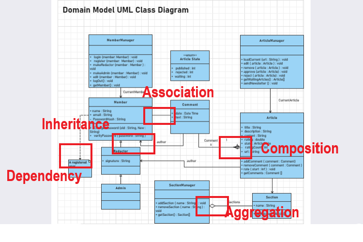
Understanding the Relationship
Developers build relationships between the actors to interpret the diagram and implement coding. These connections are denoted by different types of arrows. Here is a breakdown of what each relationship between actors means in a UML diagram.
|
Relationship |
Meaning |
Denoted By |
|
Association |
An action resulted by the behavior of an object of one class |
Solid black line |
|
Inheritance |
Child and parent relationship of two classes. For instance, Class 2 and Class 3 are subdivisions of Class 1. |
Solid black lines with closed arrows at the end, both meeting a parent class |
|
Realization |
The relationship between two classes (interface and implementation). For instance, Class 1 has the operation details, and Class 2 is responsible for carrying it out |
Two dashed black lines meet a parent class with an open arrow at the end |
|
Dependency |
One class depends on another. For instance, Class 2 is dependent on the Class 3 |
Dashed line with an open arrow at the end |
|
Aggregation |
Relationship between objects of classes. For instance, one class is part of another class. In this case, classes can exist independently of each other. |
Solid line with an unfilled diamond at the end |
|
Composition |
Type of aggregation. It determines the relationship between objects of classes that cannot exist independently. |
Solid line with a filled diamond at the end |
Conclusion
Want to make UML diagrams in half the time? EdrawMax can serve you just fine with its built-in template community and large symbol library. Moreover, its intuitive layout makes everything simpler and quicker for you. The best part is that you are getting these features in a free version.

No comments yet