Introduction
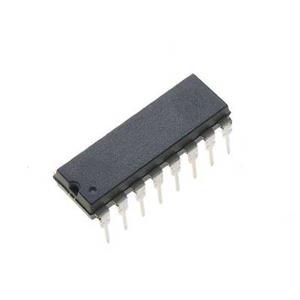
The CD4053BMT analog multiplexer is controlled digitally analog switches. It has a low ON impedance, and a very low leakage current OFF. It has three digital control inputs containing A B, C, and as well as an inhibit input. Each control input can select one of the channels, which are connected in a single-pole double-throw arrangement. The CD4053BMT multiplexer is general use and is suitable for analog and digital multiplexer and demultiplexer, signal gate, factory automation, televisions, and as well as A/D and D/A conversion.
Features
Binary Address Decoding on Chip
100% Tested for Quiescent Current at 20 V
Break-Before-Make Switching Eliminates Channel Overlap
Diagram

CAD Model

Symbol

PCB Footprints

3D Models
Specifications
Supply Chain
Factory Lead Time - 6 Weeks
Physical
Number of Pins - 16
Weight - 141.690917mg
Technical
Operating Temperature - -55°C~125°C TA
Circuits of CD4053BMT

Alternative Models
MC14053BDR2G, CD4053BM96G3, CD4053BM
Where to Use CD4053BMT?
The CD4053BMT multiplexers are a type of device which can take multiple input signals, and create a single output signal in accordance with the mode for recovery of every input signal. A multiplexer is a system that is integrated and typically comprises several data inputs as well as a single output. It is able to select one of the digital or analog input signals and then forward it. Then, the various signals are selected are sent on the identical output line.
The purpose of using the CD4053BMT multiplexer is to make the best utilization of the potential of the communication channel and also decrease the cost for the entire system. For instance, when you have two lines of telephone the frequency of communication typically exceeds 100kHz. The frequency band for each telephone signal is typically restricted by below 4kHz. It means that the bandwidth that the signal can transmit is greater than the information transmission capability of a phone.

How to Use CD4053BMT?
With the help of a multiplexer system, the multichannel data can be shared on one channel. When the flow of data over an exchanged line continues, sharing technique can yield excellent results. It is evident that this is cheaper than having a separate line of communication to each terminal. The CD4053BMT multiplexers are usually used in pairs. One is a continuous terminal and the other one close to the host. Its job is to take in the data stream that is composite, depending on channels separation the data. It sends the data to the appropriate output line.
The CD4053BMT multiplexers can affect the efficiency that the signal chain performs in a number of ways. Conductance, for instance, can create a crossing over between the two channels. Changes in temperature and signal on-resistance can cause distortion in signals. The capacitance and resistance of the multiplexer will restrict the signal's signal bandwidth. Charge injection could cause problems with transients when it changes channels, which affects the stability of the output.
Click the link to check more details
https://www.easybom.com/blog/a/an-introduction-of-the-cd4053bmt-multiplexer


No comments yet