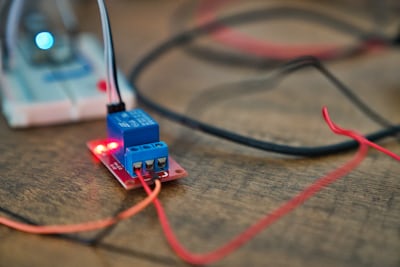
A relay is an electrical control device. It is an electrical appliance that causes the controlled quantity to undergo a predetermined step change in the electrical output circuit when the change in the input quantity meets the specified requirements. It has an interactive relationship between the control system (also called the input loop) and the controlled system (also called the output loop). Usually used in automated control circuits, it is actually an "automatic switch" that uses a small current to control the operation of a large current. Therefore, it plays the role of automatic adjustment, safety protection, and conversion circuit in the circuit.
Selection method of relay
1. First understand the necessary conditions: the power supply voltage of the control circuit, the maximum current that can be provided; the voltage and current in the controlled circuit; how many sets and types of contacts are needed for the controlled circuit. When selecting a relay, the power supply voltage of the general control circuit can be used as the basis for selection. The control circuit should be able to provide enough working current to the relay, otherwise the relay will be unstable when it is closed.
2. After consulting the relevant information to determine the conditions of use, you can search for the relevant information to find out the model and specification number of the required relay. If you have a relay in hand, you can check whether it can be used according to the data, and finally consider whether the size is appropriate.
3. Pay attention to the volume of the appliance. If it is used for general electrical appliances, in addition to considering the volume of the chassis, the small relay mainly considers the installation layout of the circuit board. For small electrical appliances, such as toys and remote control devices, ultra-small relay products should be used.
Precautions for the use of relays
1. Rated working voltage: refers to the voltage required by the coil when the relay is working normally. Depending on the model of the relay, it can be AC voltage or DC voltage.
2. DC resistance: refers to the DC resistance of the coil in the relay, which can be measured by a universal meter.
3. Pull-in current: refers to the minimum current that the relay can produce a pull-in action. In normal use, the given current must be slightly larger than the pull-in current, so that the relay can work stably. As for the working voltage applied to the coil, generally do not exceed 1.5 times the rated working voltage, otherwise it will produce a larger current and burn the coil.
4. Release current: refers to the maximum current that the relay generates to release the action. When the current in the pull-in state of the relay is reduced to a certain level, the relay will return to the unpowered release state. The current at this time is much smaller than the pull-in current.
5. Contact switching voltage and current: refers to the voltage and current that the relay is allowed to load. It determines the magnitude of the voltage and current that the relay can control, and this value cannot be exceeded during use, otherwise it is easy to damage the contacts of the relay. Use technology; it means that the coil in the relay will produce a very high reverse electromotive force when it loses current, which can easily damage the electronic devices that control it. In the process of use, it is important to consider the introduction of absorption circuits in the design circuit.
Method of testing relay
1. Measure the coil resistance: use a universal meter to measure the resistance of the relay coil in the R×10Ω gear to determine whether the coil is open. The resistance value of the relay coil has a very close relationship with its working voltage and working current, and its working voltage and working current can be calculated by the resistance value of the coil
2. Measuring contact resistance: Use the resistance file of a universal meter to measure the resistance of normally closed contacts and moving points. The resistance value should be 0; and the resistance value of normally open contacts and moving points is infinite. From this, it can be distinguished which is a normally closed contact and which is a normally open contact.
3. Determine the absorption voltage and absorption current: find an adjustable regulated power supply and ammeter, input a set of voltages to the relay, and string an ammeter into the power circuit for monitoring. Slowly increase the power supply voltage, hear the relay picking sound, note the absorption voltage and absorption current. In order to get accurate results, you can try multiple times and get the average value.
4. Measure the release voltage and release current: Connect the test as described above. When the relay is closed, gradually reduce the power supply voltage, and hear the sound of the relay releasing again. Write down the voltage and current at this time. You can also try more Several times to get the average release voltage and release current. Generally speaking, the release voltage of the relay is about 10~50% of the absorption voltage. If the release voltage is too small (the pull-in voltage is less than 1/10), it cannot be used normally, which will endanger the stability of the circuit and threaten to make the work unreliable.
Look through Easybom to find more information about the relays.


No comments yet