Introduction
The circuit for snubbing a capacitor and resistor is comprised of the resistor and a capacitor that are connected in series. The resistor is used to absorb the energy of voltage spikes, and the capacitor acts as temporary storage for the energy. Thus, the possibility of sudden changes in the electrical flow damage is reduced.
Why is an RC Snubber Needed?
A voltage spike occurs when the power source experiences an intermittent rise in the voltage. The issue with electricity and voltage spikes is that it could cause your electronics to fail and break down without you even noticing the problem until it is too late. This can include your refrigerator, stove, television, computer, and many more. These RC snubbers are essential as they provide quick protection from sudden fluctuations in voltage. They convert the energy into heat energy, rather than causing problems such as electrical surges or melting circuits. These RC snubbers are simple to install and can be put on your electronics. Additionally, they can help reduce the EMI noise and improve the reliability of your circuit.
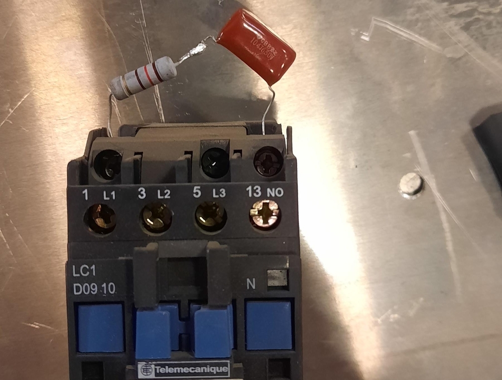
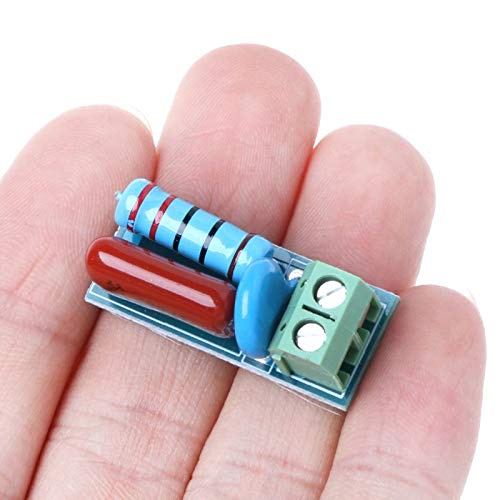
(RC snubber that is attached at the end of the wire for it to "snub" any current surges)
RC Snubber Circuit Working Principle
The idea that drives the operation of an RC snubber circuit lies simple. A fluctuating voltage or current is transmitted to a wire that is connected to an electronic component. there is a good chance that it will harm the circuit inside. An RC snubber circuit reduces the current and stops any damages.
A relay or SCR controller can be utilized to change the resistance provided by this circuit, limiting the flow of electricity through it. As the voltage rises it decreases the resistance and is reversed. The capacitors in parallel will be activated when voltage increases and are able to accumulate additional charge. In turn, the resistance of resistors decreases, and consequently, the current in the circuit is reduced.
Therefore the electric capacitor can be utilized to limit or absorb abrupt increases in voltage. The purpose that a resistor serves is to disperse or reduce the energy of magnetic flux through this process to ensure that there is no harm done.
How to Design an RC Snubber
First, determine the voltage rating of this switch. It is important to determine the maximum rating for current. must be taken into consideration along with the minimum rating for the resistor. Then, think about what the frequency of switching would be in this particular circuit. Then, consider the dimensions of capacitor you would like to use for this circuit.
If you've determined what frequency to use then you need to find out what the voltage of RMS is. It is done either such as by calculating it or using graphs. After the RMS rating is calculated and then it can tell the amount of current that is going to be flowing through your circuit. Next, you need to calculate the duration of the circuit that is the reverse of frequency. Then, divide that number by the RMS rating of the voltage.
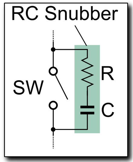
(Typical diagram for one RC snubber)
Resistor Selection
Another method of determining the resistance value you need is choosing the span. It is a matter of choosing the amount of distance you want to be from the maximal current capacity you would like to be once it reaches zero amps. Then, you can decide what the minimum amount of current that you can run through your system will be. The formula for resistor value is determined using the method of multiplying the intended length by 0.732 that needs to result in a number that, when multiplied by your maximum current rating is equal to or exceeds your voltage rating for RMS. Once you have determined the resistor value that is most suitable for your particular circuit It is recommended to not exceed the limit of this value.
Capacitor Selection
Then, you must decide on the size of the capacitor needed to provide the right amount of current to your circuit. Three formulas can be utilized however they all begin by determining what capacitance is required to cut the voltage on the resistance to half. Once you have this information determine how much ripple voltage will add to the final after which you can select a capacitor that can manage that.
Notes for Applying RC Snubber Circuits
1. In accordance with the RC snubber diagram the dissipation of resistance should be identified and properly handled in order to ensure an acceptable degree of heat. It is possible to use this equation to calculate the equation:
Loss=CxVIN2xFSW
Here, the C is for Capacitance, and it is the V In=Supply Voltage, and F SW=the frequency of the switch.
2. If a snubber circuit is utilized, efficiency will be decreased if the transition from one state to the next occurs more slowly. This is why the level of noise as well as energy efficiency has to be considered.
Summary
In short this way, it is said that the RC snubber is a kind of circuit that is able to absorb voltage spikes, and keeps them from causing damage to equipment or circuits. This example of an inverter shows an easy RC snubber circuit. It is possible to configure the circuit to snubber in a variety of ways to meet your requirements.

No comments yet