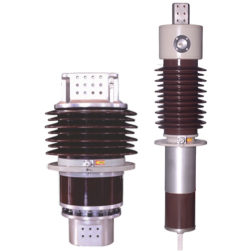
An insulating device called a transformer bushing makes it easier for an energised conductor to pass through the grounded tank of the transformer. A bushing may be made with a provision for a separate conductor to be drawn through its centre, sometimes known as a draw-lead or draw-rod bushing, or it may be built with the conductor already built in, in which case it is known as a bottom-connected bushing.
The two main types of bushing construction are capacitance-graded and solid or bulk type (sometimes called condenser type). The bushings used for a transformer's low voltage winding(s) are frequently of the solid kind with an insulator made of porcelain or epoxy. The high voltage winding of a transformer uses bushings that have been capacitance-graded for higher voltage ratings.
In contrast to a solid type construction, a capacitance-graded transformer bushing has conducting layers put into the insulation separating the centre conductor from the bushing's insulator (housing) at predefined radial intervals. These numerous conductive inserts produce capacitive components that connect the bushing's centre conductor to ground. To ensure a more even distribution of voltage across the surrounding insulation system in the bushing, they are designed to manage the voltage field around the centre conductor.
Between the conductor and the insulator in solid type bushings, electrical grade mineral oil is frequently utilised. This oil may be contained within the bushing or shared with the transformer. Typically, oil-impregnated paper (OIP), resin-impregnated paper (RIP), and resin-bonded paper are used as insulation in a capacitance-graded bushing (RBP). Mineral oil, which is often integrated into the bushing, is also used in capacitance-graded bushings.
Transformer asset owners are very interested in the health of the transformer bushings because bushing failures are frequently cited as one of the leading causes of transformer failures. The most common bushing failure modes are moisture infiltration, electrical flashover, lightning strike, short-circuited capacitance-graded layer(s), incorrect application of the bushing, corrosive sulphur, broken connection between ground sleeve and flange, and broken tap connection. The integrity of the bushings is determined by the electrical field tests that are performed after that.
Bushing diagnosis
- Tan delta, power factor, dissipation factor, and capacitance at line frequency
Tan delta/power factor/dissipation factor evaluates the robustness of the bushing's insulation system. A capacitance-graded bushing needs to pass the C1 and C2 tests. The main core insulation of the bushing is examined using a C1 power factor/dissipation factor test, whilst the insulation in the bushing tap compartment, as well as the outermost main core insulating wraps and surrounding filler material, are evaluated using a C2 measurement. When pollutants such as moisture or other impurities gather at the flange as a result of, say, a damaged or defective top terminal gasket, C2 frequently acts as an early warning system.
- Capacitance:
The physical integrity of the bushing is evaluated concurrently by the measurement. Increases in C1 capacitance, for instance, may be signs of short-circuited capacitance-graded layers in the bushing, which would necessitate replacing the bushing right away.
- Tan delta, power factor, and tip-up dissipation factor
Tan delta/power factor/dissipation factor tip-up, which examines whether power factor/dissipation factor alters as the test voltage changes, may be helpful in identifying loose connections or localised defects. When used in conjunction with DFR, it may also be successful in identifying ageing effects.
- Power factor/dissipation factor with variable frequency (VFPF):
A subset of the frequencies used in a DFR measurement are used in this test, which consists of a collection of power factor/dissipation factor measurements (e.g., 15 – 500 Hz). In contrast to difficulties like top terminal looseness and PD generating type issues, conductive impurities are easily recognised at low frequencies (15 Hz and lower) (500 Hz).
- Test your hot collar:
For solid type bushings without taps, a hot collar test is frequently used and is useful for identifying deterioration, contamination, low compound or liquid levels, and compound voids (if applicable). As a complement to the C1 and C2 experiments on capacitance-graded bushings with taps, it might also be useful.
- Dielectric reaction to frequency (DFR):
Strong indications of bushing insulation breakdown in bushing diagnostics include a prominent temperature dependence (i.e., higher power factor/dissipation factor at high temperatures). The capacity to execute individual temperature correction of recorded 50/60 Hz power factor/dissipation factor to values at a reference temperature (20oC) is provided by DFR measurements. If the bushing is excellent or not, it can be determined by comparing the recorded temperature dependency with the temperature correction data provided by the bushing manufacturer. Bushing moisture assessment using DFR readings is possible.
- Partial release (PD)
- DGA:
Some asset owners take oil samples from bushings with varying capacitances in order to do dissolved gas analysis studies. This method of treatment is uncommon.

No comments yet